Arithmetic circuits come to us from a field of research called computational complexity theory, and are the standard model for computing polynomials. An arithmetic circuit is an abstract concept, but it operates like a logic circuit: it takes variables and numbers as inputs, which go through arithmetic gates such as "add" or "multiply", as in the image below, where the boxes are inputs and the circles are gates. (source)
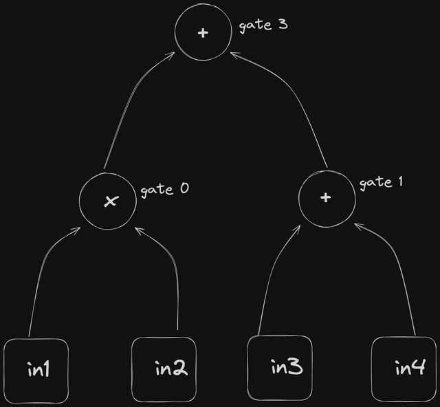
The design approach here is very similar to the other implementations in this book:
- Design the structural interface and data structures
- Comment out the steps needed to implement this interface
- Implement the complete interface
- Write unit tests :)
You can find the complete code implementation here.
Interface and Data Structures
This circuit needs just one method, responsible for evaluating the circuit on some given input.
pub trait CircuitInterface {
    fn evaluate<F>(&self, input: &[F]) -> CircuitEvaluation<F>
    where
        F: Add<Output = F> + Mul<Output = F> + Copy;
}
Data structures
#[derive(Clone, PartialEq, Eq, Hash, Default, Debug)]
pub struct Circuit {
    pub layers: Vec<CircuitLayer>,
}

#[derive(Clone, PartialEq, Eq, Hash, Default, Debug)]
pub struct CircuitLayer {
    pub layer: Vec<Gate>,
}

#[derive(Clone, PartialEq, Eq, Hash, Debug)]
pub struct Gate {
    pub g_type: GateType,
    pub inputs: [usize; 2],
}

#[derive(Clone, PartialEq, Eq, Hash, Debug)]
pub enum GateType {
    Add,
    Mul,
}Circuit: The entire arithmetic circuit. It contains multiple layers of gates. Layer 0 is the output layer, and the last layer is the one closest to the inputs.CircuitLayer: A single layer within the circuit, containing multiple gates. This organizes gates into layers, which helps with implementing and understanding the flow of computation.Gate: An individual gate within a layer.g_typeindicates the operation the gate performs (AddorMul).inputsholds two indices, which refer to outputs of the layer below it or, for the last layer, to the input values.GateType: An enum defining the operations a gate can perform.
Here is how this circuit is constructed:
// sample circuit evaluation
//        100(*)        - layer 0
//       /      \
//   5(+)_0    20(*)_1  - layer 1
//   /  \      /  \
//  2    3    4    5
let layer_0 = CircuitLayer::new(vec![Gate::new(GateType::Mul, [0, 1])]);
let layer_1 = CircuitLayer::new(vec![
    Gate::new(GateType::Add, [0, 1]),
    Gate::new(GateType::Mul, [2, 3]),
]);
let circuit = Circuit::new(vec![layer_0, layer_1]);
Interface Implementation
This implementation evaluates the circuit on given input values, computing the output of each gate layer by layer, starting from the inputs.
The evaluate method takes a slice of inputs and returns a CircuitEvaluation<F>, where F is any type that supports addition and multiplication. The CircuitEvaluation struct holds the result: a vector of layers, where each layer is a vector of gate outputs.
impl CircuitInterface for Circuit {
    fn evaluate<F>(&self, input: &[F]) -> CircuitEvaluation<F>
    where
        F: Add<Output = F> + Mul<Output = F> + Copy,
    {
        let mut layers = vec![];
        let mut current_input = input;
        layers.push(input.to_vec());

        for layer in self.layers.iter().rev() {
            let temp_layer: Vec<_> = layer
                .layer
                .iter()
                .map(|e| match e.g_type {
                    GateType::Add => current_input[e.inputs[0]] + current_input[e.inputs[1]],
                    GateType::Mul => current_input[e.inputs[0]] * current_input[e.inputs[1]],
                })
                .collect();
            layers.push(temp_layer);
            current_input = &layers[layers.len() - 1];
        }

        layers.reverse();
        CircuitEvaluation { layers }
    }
}
How it works
- Initialization:
layersis created to hold the results of each layer,current_inputis set to the input, and the input is pushed as the first entry oflayers. - Layer processing: The method iterates over the circuit layers in reverse with
self.layers.iter().rev(), because the last layer is the one that reads the inputs. Each gate is evaluated according to its type (GateType::AddorGateType::Mul), the results are collected intotemp_layerand pushed ontolayers, andcurrent_inputthen points at this new layer. - Finalization:
layersis reversed, so the result runs from output to input:layers[0]is the circuit output and the last entry is the original input. This matches the layer numbering of the circuit.
Here is sample code for building and executing a Circuit on some input. The result is [[100], [5, 20], [2, 3, 4, 5]].
let layer_0 = CircuitLayer::new(vec![Gate::new(GateType::Mul, [0, 1])]);
let layer_1 = CircuitLayer::new(vec![
    Gate::new(GateType::Add, [0, 1]),
    Gate::new(GateType::Mul, [2, 3]),
]);
let circuit = Circuit::new(vec![layer_0, layer_1]);
let input = [
    Fr::from(2u32),
    Fr::from(3u32),
    Fr::from(4u32),
    Fr::from(5u32),
];
let evaluation = circuit.evaluate(&input);